

Microteck V8 PCB क्या है? (Full Guide हिंदी में)
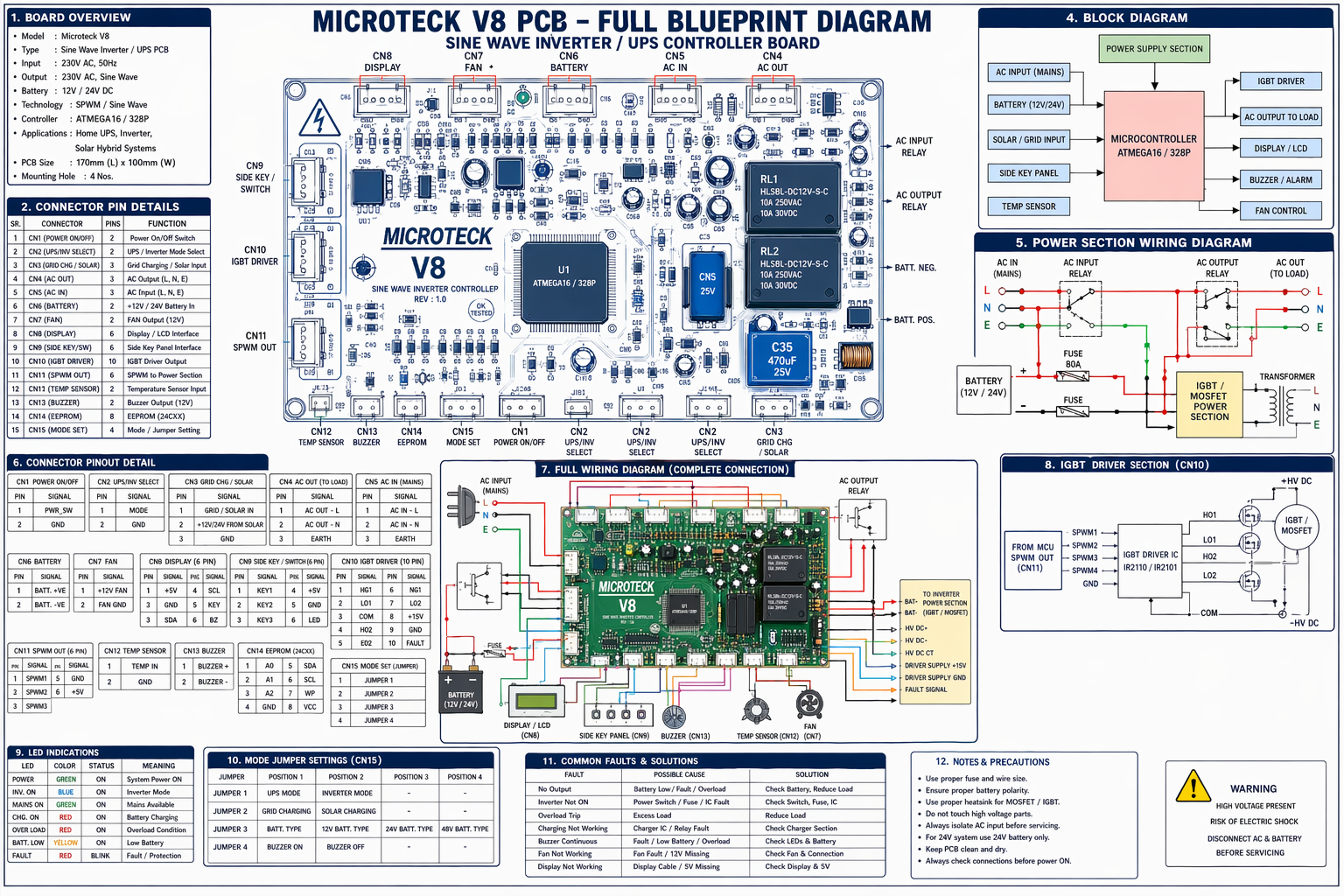
Microteck V8 PCB एक Sine Wave Inverter / UPS Controller Board है, जो बैटरी की DC सप्लाई को AC (220V) में कन्वर्ट करता है। यह PCB घरों में इस्तेमाल होने वाले इन्वर्टर का मुख्य दिमाग होता है।
1. PCB का बेसिक ओवरव्यू
- Input: 230V AC
- Battery: 12V / 24V
- Output: 230V AC (Pure/Sine Wave)
- Controller: ATmega16 / ATmega328
- Technology: SPWM (Sine Wave PWM)
यह PCB तीन मुख्य काम करता है:
- Battery Charging
- DC to AC Conversion
- Protection & Control
2. PCB के सभी कनेक्टर (CN1 – CN15)
CN1 – Power ON/OFF
- Inverter को ON/OFF करने के लिए
CN2 – UPS / Inverter Select
- Mode change (UPS Mode / Normal Mode)
CN3 – Grid / Solar Charging
- Solar या AC से charging control
CN4 – AC Output (Load)
- Output supply load को जाता है
CN5 – AC Input (Mains)
- Main बिजली यहाँ से आती है
CN6 – Battery
- Battery + और – कनेक्शन
CN7 – Fan
- Cooling fan connection
CN8 – Display
- LCD / LED display
CN9 – Side Key / Switch
- Buttons / Control keys
CN10 – IGBT Driver
- MOSFET / IGBT control signal
CN11 – SPWM Output
- PWM signal driver को देता है
CN12 – Temperature Sensor
- Heat monitoring
CN13 – Buzzer
- Alarm system
CN14 – EEPROM
- Data storage
CN15 – Mode Jumper
- Settings control
3. Power Section Wiring (सबसे जरूरी )
AC Input Wiring
- Phase (L) → CN5
- Neutral (N) → CN5
- Earth (E) → Ground
यह supply पहले relay में जाती है
Battery Wiring
- Battery + → CN6
- Battery – → CN6
गलत polarity = PCB damage
Working Flow
AC Available → Direct Load (Bypass Mode)
YOUR ADSENSE CODE HERE
AC Fail → Battery → MOSFET → Transformer → AC Output
4. Relay System (Auto Switching)
AC Input Relay
- Decide करता है: AC या Inverter
Output Relay
- Load switching करता है
Light आते ही inverter बंद और direct supply चालू
5. Inverter Power Section (Core Working)
Step-by-Step:
1. PWM Signal
- Microcontroller sine wave PWM बनाता है
2. Driver IC
- PWM signal amplify करता है
3. MOSFET / IGBT
- High speed switching
4. Transformer
- 12V/24V → 220V AC
6. Microcontroller (Brain of PCB)
Microcontroller (ATmega16/328) का काम:
- Battery voltage monitoring
- AC detection
- Relay control
- PWM generation
- Fault protection
7. Sensor & Protection System
Temperature Sensor
- Overheat होने पर shutdown
Protection Types:
- Overload
- Short Circuit
- Low Battery
- Overcharge
8. Fan, Buzzer & Display
Fan (CN7)
- Heat बढ़ने पर ON
Buzzer (CN13)
- Alarm देता है:
- Low battery
- Fault
Display (CN8)
- Status दिखाता है:
- Charging
- Output
- Error
9. IGBT Driver Section (CN10)
- Driver IC: IR2110 / IR2101
- Gate drive voltage: 10–15V
यह section inverter का सबसे critical हिस्सा है
10. Mode Jumper Settings (CN15)
- UPS Mode
- Inverter Mode
- Battery Type
- Buzzer ON/OFF
11. Common Problems & Solutions
No Output
- Battery check
- MOSFET check
- Driver check
Charging नहीं हो रही
- Relay
- Charger circuit
Inverter ON नहीं हो रहा
- Power switch
- Fuse
12. Repair Tips (Technician Level )
- CN10 loose = inverter dead
- MOSFET short = fuse blow
- Relay click नहीं = control issue
- Low battery = no output
Safety Tips
- 220V dangerous है
- Direct touch न करें
- Testing में bulb series use करें
निष्कर्ष (Conclusion)
Microteck V8 PCB एक advanced inverter control board है जो:
✔ Automatic switching
✔ Battery charging
✔ Pure sine wave output
✔ Multiple protections
provide करता है।
अगर आपको इसकी wiring और working समझ आ गई, तो आप आसानी से inverter repair और troubleshooting कर सकते हैं।
Add a review
Your email address will not be published. Required fields are marked *